.JPG)
.JPG)
.JPG)
.JPG)
.JPG)
DRSSTC
Last Updated: 2007-11-28
DRSSTC (Double Resonant Solid State Tesla Coil) the primary current feedback driver is Steve Ward's design.
Updated Specs:
| IGBT | 2x Powerex CM300DU24F (300A 1200V) |
| Input Filtering | 2x 400V 3300UF electrolytic capacitors in series for voltage doubler - I wanted more but they wouldnt fit in the case. |
| Input Voltage | 240V from 10A variac - pushing the variac I know.. but its all I have. |
| Primary | 16" diamter 10 turn 5/8" OD copper tubing on 15" sewer pipe |
| Secondary | 8" by 45" winding of 28 gauge = 3280 turns Fres with toroid = 38Khz |
| Tank Capacitor | 60x CDE 942C .15uf 2kv in 15 strings of 4 = .56uf 8kv |
| Toroid | 7" by 36" dryer duct toroid |
|
First day running Sec is raised up 4.5 inches to stop pr/sec sparks. |
|
Target moved out to 7 feet |
|
Measuring.. Im 6 feet tall for comparison. |
|
Streamers to air.. All i changed in this pic was to bend the breakout point slightly upwards.. |
|
Power arc to strike rail. |
Warning: the following may be outdated
System Diagrams:
 |
Controller Schematic Not completely identical to the PCB because of the added indicator LEDs that I now use. |
 |
Controller PCB Slightly outdated PCB design for the controller. One sided for ease of making the PCB. |
 |
Gate Driver Schematic This gate driver design will work up to 150khz or so, much over that and things start to overheat. +30V - 15V drive with optoisolator. The optos do add considerable delay and for new designs I recommend using faster isolators. The new TI capacitve coupling ones are amazingly fast, but will need a UCC3721 buffer and 5v supply. |
 |
Gate driver PCB Again, although this is the way I built the PCB, there are some errors and revisions that would need to be made. These are mostly for my own reference. |
 |
Audio Interrupter (works well) This relatively simple circuit works well and allows me to hook up an electronic keyboard, mp3 player, or any other audio source.. The DRSSTC will only reproduce very simple tones so full on songs dont sound like anything good.. But simple MIDI files are fun.. same goes with simple keyboard tunes. |
 |
Audio interrupter PCB PCB for above design, no part numbers |
Update - New gate driver and H-Bridge:
 |
Isolated DC-DC converter transformer |
 |
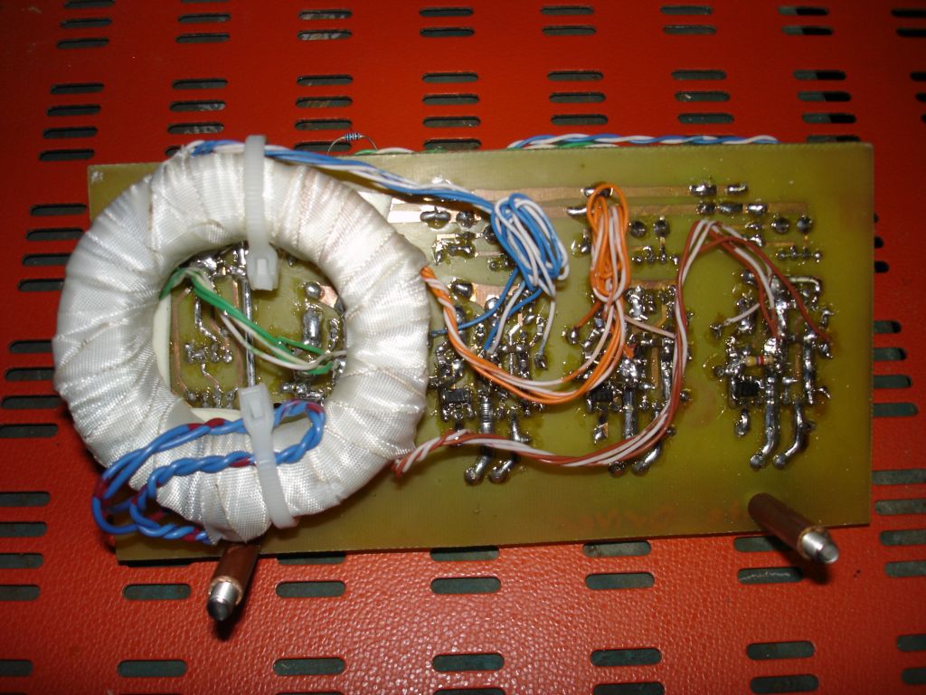
Transformer with fiberglass tape |
 |
Top View Gate Drive Board |
 |
Bottom View Gate Drive Board |
 |
Side View Gate Drive Board |
 |
Bottom View after some modification |
 |
Top View, Installed |
 |
Left Side View, Installed |
 |
Overall system, including new H-Bridge |
 |
Top View System |
 |
Top/Front System |
Very old System Pictures:
 |
H-Bridge during construction. Etched PCB with 1/16" copper flashing high current buss bars. |
 |
3 Phase power filter |
 |
H-bridge bolted to IGBT's |
 |
Module layout during development |
 |
Some components test mounted |
 |
Current sense transformers and high current output socket assembly |
 |
Another view of above. |
 |
Another view with plug assembly. |
 |
Capacitor bank: 0.45uf 4000V DC rating. Each capacitor is .15uf 2000V. |
 |
Test layout with first gate drive transformer setup. This transformer may have worked if i had driven it with high current MOSFET's. I was using little 9A 8 pin DIP drivers that were inadequate. |
 |
More components mounted. That board in the front is the main feedback driver circuit along with over current protection circuit. |
 |
Wooden case built for tesla coil, holds standard 19" rack mount enclosures. |
 |
Same but with a clear varnish. |
 |
More complete layout. On the left you can see the slow start resistor and the power relay that bypasses it once the filter capacitors are charged up. Just to the right of that the ferrite core with red and black wiring is an input line filter. |
 |
Interrupter Circuit. |
 |
Interrupter circuit in case. |
 |
Test fitting components in wooden box. |
 |
Same. |
 |
Gate driver being built. The TO-220 drive chips are IXYS brand IXDD414. Supposedly capable of 14A. On the left of the circuit board is a simple MOSFET push pull DC-DC converter to provide isolated 15V for each driver. |
 |
New gate drive board installed. Bottom left is a switch mode 120-240V AC input to 12V DC converter. |
 |
First Light. |
 |
Close up with lights off. |